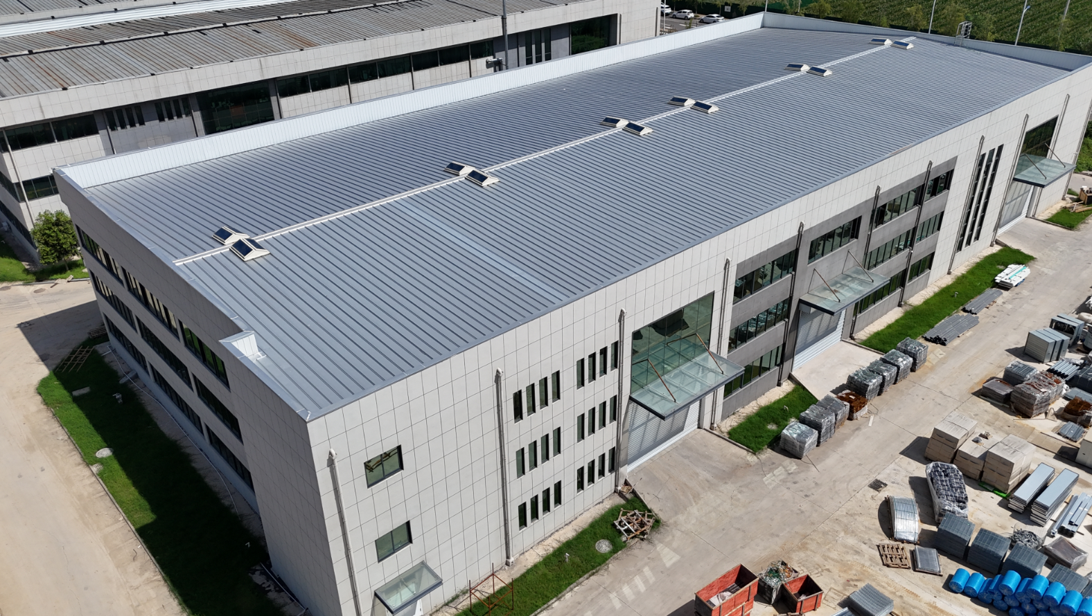
Layout Design for Steel Fabrication Workshops: Engineering Rules, Crane Integration, and Lean Flow Optimization
Key Takeaway: Optimizing a steel fabrication workshop layout is not just about placing machines; it is about aligning structural columns, crane runway beams, and high-load foundation anchors with the physical flow of heavy steel. By integrating Grid-Forming Crane Engineering and U-shaped Lean Cells early, fabricators can eliminate up to 22% of material rehandling costs and avoid structural retrofits.
?️ Value Stream Mapping (VSM) for Heavy Steel: Eliminating Hidden Micro-Delays
In structural steel fabrication, material movement is the single largest non-value-added cost. Moving a 12-meter H-beam weighing over 2 tons requires crane operation, rigger coordination, and floor clearance.
A high-performing layout must be modeled on material-handling takt time, mapping every step from raw plate receiving to final coating.
When fitting stations are placed far from cutting tables, overhead cranes spend excess duty cycles "shuttling" rather than positioning.
To eliminate this waste, workshops should design contiguous, unidirectional flow paths. A unidirectional flow ensures that once raw steel enters the bay, it never backtracks past a completed workstation, reducing crane waiting times and floor congestion.
?️ Crane-Structure Integration: The Foundation of Heavy Lift Safety
The overhead crane system is the arterial network of a steel workshop. Integrating crane runways at the structural design stage prevents structural overloading, excessive runway wear, and column deflection.
When designing the building skeleton to match crane capacities, engineers must adhere to rigid mechanical benchmarks:
| Engineering Parameter | Industrial Standard / Benchmark | Operational Impact on Steel Workshop Layout |
|---|---|---|
| Column Spacing (Bay Length) | 6.0m to 9.0m optimized spacing | Aligns with standard steel member lengths; reduces runway beam steel consumption. |
| Runway Beam Deflection | Limit to L/1000 for cab-operated cranes (GB/T 14405 / CMAA 70) | Prevents crane "coasting" or braking slippage, ensuring precise structural assembly alignment. |
| Clear Hook Height | Minimum 6.5m to 8.0m clearance above floor level | Permits flipping of large portal frames and truss assemblies without hitting floor equipment. |
| Dynamic Load Allowance | 20% vertical impact factor added to crane wheel loads | Prevents long-term concrete fatigue and rail misalignment at welding/assembly zones. |
?️ Cellular Layouts & 5S: Minimizing Crane Dependence
While overhead cranes are essential, over-reliance on them creates massive bottlenecks. Grouping cutting, punching, bending, and localized welding equipment into U-shaped production cells dedicated to specific product families (such as connection plates, gussets, or purlins) allows materials to move via gravity rollers or light jib cranes.
By organizing this sequence within a tight 12-meter radius, the travel distance for auxiliary parts collapses by over 40%.
Applying 5S (Sort, Set in order, Shine, Standardise, Sustain) within these cells ensures that magnetic clamps, grinding discs, welding nozzles, and testing gauges have dedicated, color-coded locations. This organization reduces non-value-added tool searching time from minutes to seconds.
? Anchoring the Layout Around Fixed Process Points
Every steel workshop has "immovable anchors"—high-mass, high-utility equipment that cannot be easily relocated. The layout must be built outwards from these fixed coordinates:
CNC Plate Processors & Heavy Drilling Lines
These machines require deep concrete foundations (often 1.0m to 1.5m deep with reinforcing rebar meshes) to absorb high-frequency machining vibrations. Their placement must integrate chip-conveyor exit paths and heavy material loading zones.
Shot Blasting & Painting Enclosures
These structures require isolated ventilation ducts, dust filtration chambers, and explosion-proof electrical zones (complying with ATEX / NFPA standards). They must be placed at the far exit of the fabrication line to prevent metallic dust from contaminating wet paint coatings.
Mezzanines & Tool Cribs
Utilize vertical space above offices or low-clearance assembly zones for hardware storage (bolts, shear studs, welding wire), keeping the primary crane-covered floor completely clear for heavy fabrication.
? Case Study: Resolving Crane Congestion in a Portal Frame Plant
During a lean layout overhaul for a structural steel fabrication plant producing 1,500 tons of portal frames monthly, field engineers observed that the fitting and welding stations experienced a 28% idle time rate, with workers waiting for the main 10-ton overhead crane to flip columns for double-sided welding.
The Solution:
-
The engineering team installed wall-mounted 1.5-ton jib cranes with a 180-degree sweep at each welding bay, dedicated solely to rotating and flipping components under 1.5 tons.
-
The main overhead crane was reserved strictly for transporting large assemblies between major fabrication zones.
-
Roller conveyor lines were integrated to feed cut sections directly into the fitting bays.
The Result:
The workshop realized a 24% increase in daily throughput, crane waiting times dropped to near zero, and the overall cost per ton of fabricated steel decreased by 14.5% over a 12-month period.
? Pre-Erection Validation Checklist for Plant Engineers
Before pouring concrete or erecting structural steel columns, plant developers should run through this design checklist to ensure operational flexibility:
| Layout Check Item | Minimum Verification Standard | Action If Non-Compliant |
|---|---|---|
| Aisle Widths | Minimum 4.5m width for primary forklift and transport lanes | Redesign column spacing or adjust material staging area boundaries. |
| Door Clearances | Minimum 5.5m width x 6.0m height for raw material and shipping bay doors | Resize structural steel door lintels to prevent transport damage. |
| Welding Power Distribution | Overhead busway bus ducts with drop cords at 6.0m intervals | Avoid laying high-voltage welding cables across pedestrian aisles. |
| Foundation Anchors | Soil bearing capacity verified to 150 kPa minimum under CNC areas | Install deep piles or isolated foundation slabs before floor pouring. |
Table of Contents
-
Layout Design for Steel Fabrication Workshops: Engineering Rules, Crane Integration, and Lean Flow Optimization
- ?️ Value Stream Mapping (VSM) for Heavy Steel: Eliminating Hidden Micro-Delays
- ?️ Crane-Structure Integration: The Foundation of Heavy Lift Safety
- ?️ Cellular Layouts & 5S: Minimizing Crane Dependence
- ? Anchoring the Layout Around Fixed Process Points
- ? Case Study: Resolving Crane Congestion in a Portal Frame Plant
- ? Pre-Erection Validation Checklist for Plant Engineers